¶ Tunning essentials
As the antenna is definitelly a non-linear device which is also affected by reflections and parasitic capacitance, tunning proceedures and results may vary with:
- ambient enviroment
- pole type
- pole height
- cable length
- temperature and humidity
- tuned frequency
- presence of humans in close proximity to the antenna
- etc....
This means, that transmissition antennas tunning for a particulary frequency cannot be the same in differrent places. There is more physics than mathematics in setting up antennas. So probably the easiest and recommended procedure is to use experimental values measured "in the office" and do final tunning in field. To do this pre-measuremnt:
- set up testing pole similar to the final pole to be used in the field (material, size, height)
- find safe and flat open space (no close buildings, cars, etc) where it's easy to handle pole and take measurement.
- try to simulate final condition as best (temperature, no rain...)
- follow tunning procedure to find best antenna tip and radiators length
- note those lengths for engineers who are going into the field for installations. They may use those values as starting
- use real cable which is going to be used with antenna in the field for tunning
![]() Note: do not cut antenna rods yet! The length may get slightly changed in a field and it's not easy to enlarge them back! Let the tip be cut in field after final tests with BB3 in real environment!
Note: do not cut antenna rods yet! The length may get slightly changed in a field and it's not easy to enlarge them back! Let the tip be cut in field after final tests with BB3 in real environment!
As you are going to use in all installations the same type and pol length, cables, antennas and transmitters, with a piece of good luck, setting to the pre-tested tip and radiator lengths should work. For best functionality, use 1,0mm as an accuracy for tip and radiators measurement. Note that all of three radiators should be at the same length.
¶ Using NANO VNA for antenna tunning
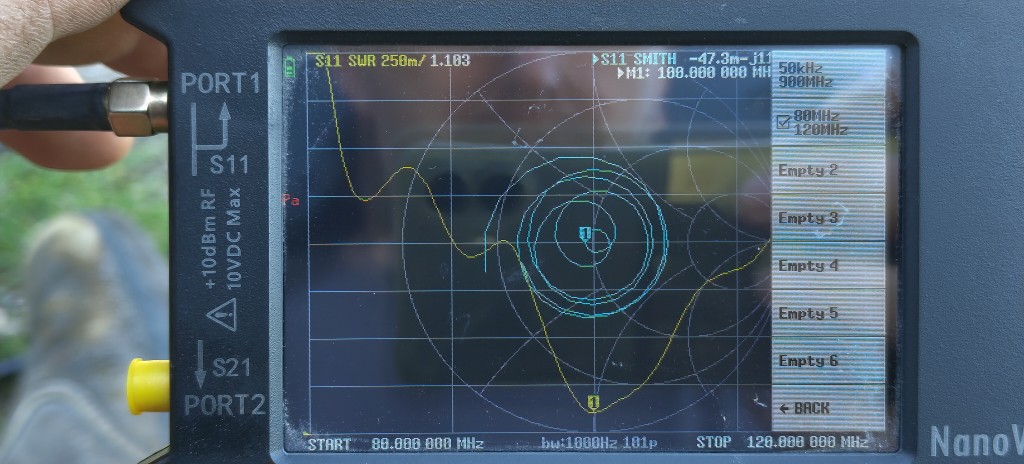
All engineers should have Nano VNA device received in their packages. This tool suppose to be preconfigured already for use in FM band. If not, full VNA configuration availabile here. To use preconfigured preset:
- Swith on NANO VNA
- touch right side of the display, menu should appear and press RECALL
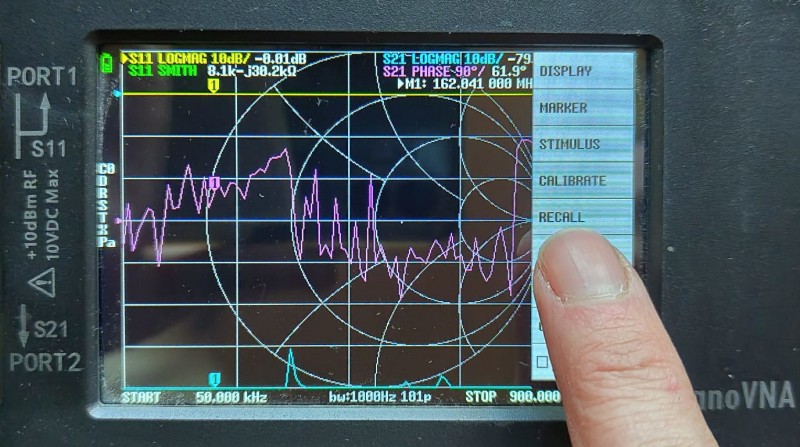
- touch 80-120MHZ preset
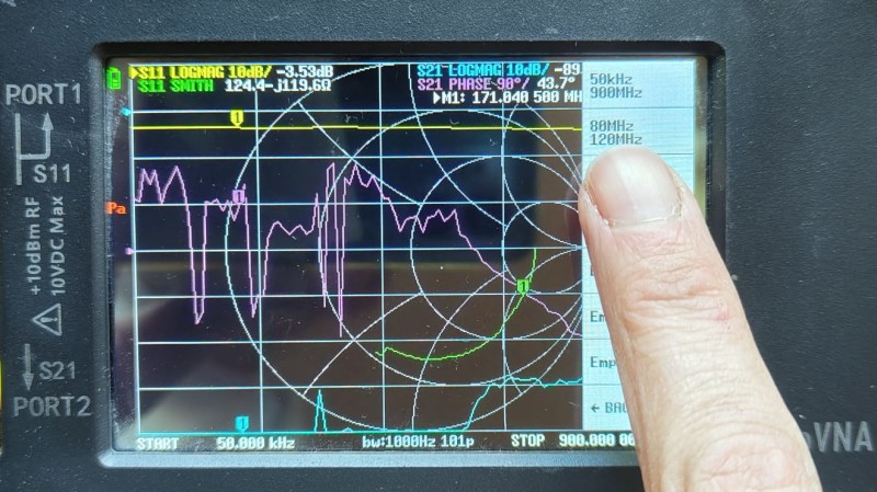
- press BACK
And it's ready to use.
¶ FM band antenna tunning
If you imagine that the FM spectrum is from 87,5MHz to 108MHz, it's unbelievable 20MHz bandwith that means we have to be able to tune-up antenna in 20% range. That's pretty much. TO be clear, there is only let's say "center band" which is relativelly easy to tune up. Lets say frequencies around 95-100MHz can be usually easilly tunned and changing the length equals mathematic expectations. We may measure "calibrated" tips and found that changing the tip length for +/- 4mm relusts in changing tunned frequency for -/+ 1MHz. As far we go of the center, situation is more "tricky" as the antenna is non linear device and you have to change not just tip length, but even radiator lengths to get best results. And, usually iterate a few times.
What are our "usefull results"?
- SWR < 1,5 (less than 2W of reflected power @50W of forward power)
- sharp bandgap arounddesired requency @SWR mentioned
What are our "best results"?
- SWR < 1,2 (less than 0,5W of reflected power @50W of forward power)
Why this is so important? Let you imagine that we measure SWR = 1.9 when you have forward power of 50W. What this means?
- you have reflected power of 5W which goes back to the transmitter
- so you radiate just 45W but trasnsmitter must produce +5W more to cancel reflected power and it results in a 10W of heat directly at the transmitter output filters and transistor(s)
- this means that your transmitter with regulation must produce 10W more to cancell reflection and another 5,5W in addition to get 50W radiated
- according to common transmitter efficiency which is around 40% usually ,this means that transmitter must consumpt more than 30W of the power more to get 50W radiated instead of 45W @SWR 1.9
- also, with common supply chain efficiency of cca 75%, power supplies must produce more than 40W of the power for transmitter to get 50W @SWR = 1,9
And this all power is just additional HEAT that must be radiated or blowed by fan out off the transmitter and which is additional load for power supplies, batteries etc. So to increase radiated power of just 5W caused by reflected power, affects in cca 10x more produced heat at the thransmitter side. And that is really danger. We have experiences that SWR < 1.2 can be achieved with some repetitive tunnings and SWR < 1,5 we can chieve relatively easy even if antenna is not perfectly ballanced.
¶ Tunning tools
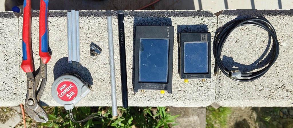
You should have a few tools in your package to tune antenna:
- Nano-VNA analyser
- Tiny-SA (optional)
- SMA-M to N-F short cables
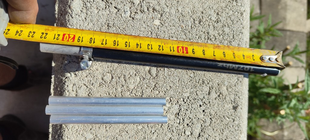
- measuring tape (not in a package)
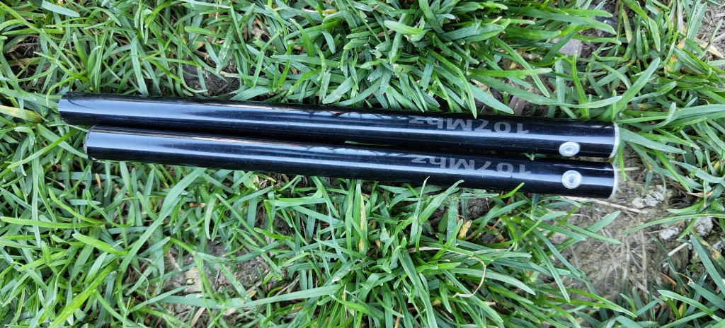
- tunned antenna tips
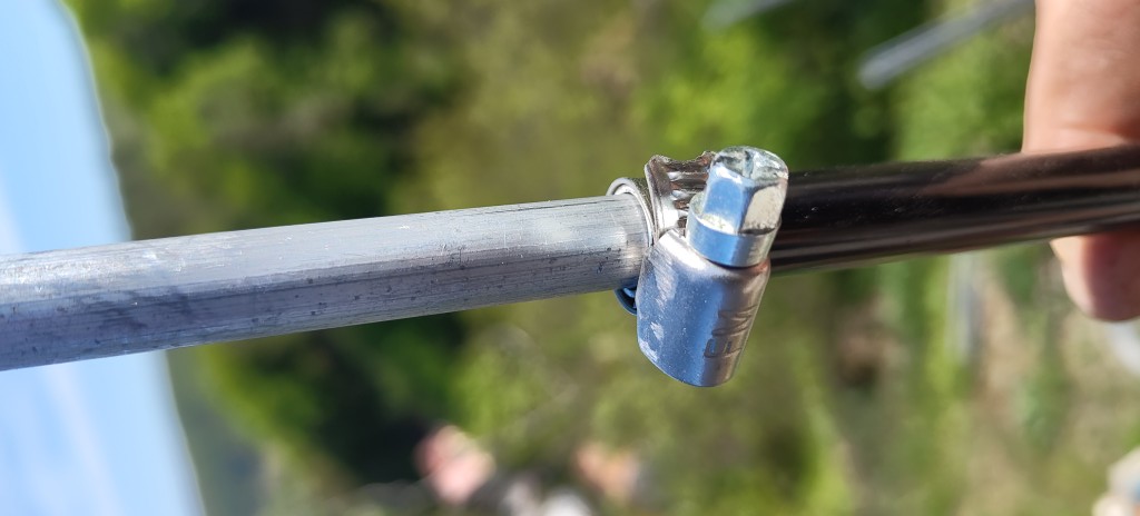
- fastenning ring (hose clamp)
- adjustable antenna rods
- extension tubes for raditors
- pliers (you can use coaxial cable crimping tool with adequate head)
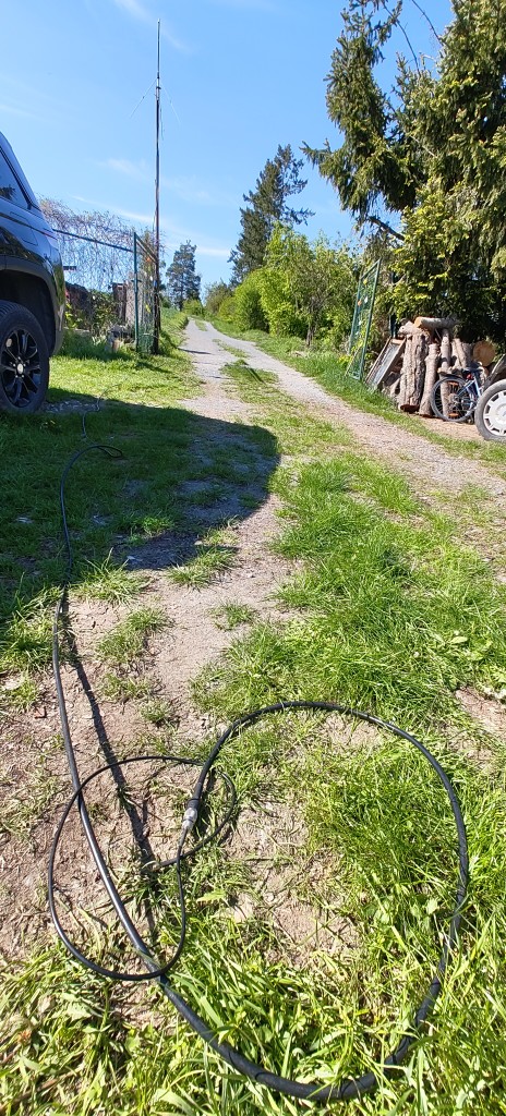
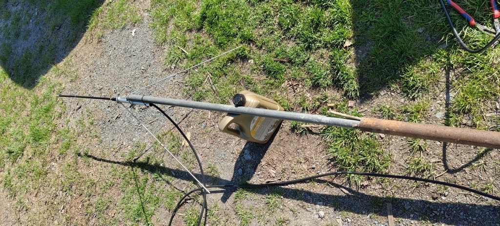
¶ Finding a place
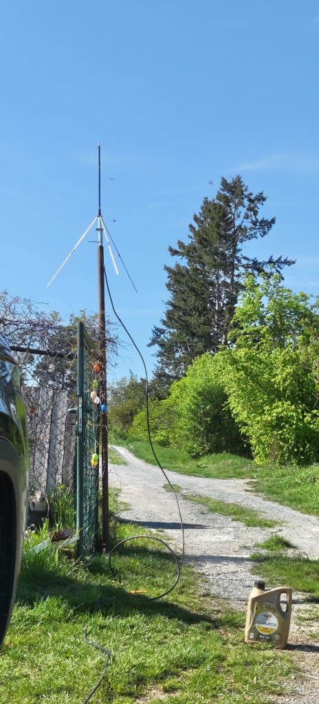
Suitable place for antenna tunning is essential. The place should be away from all buildings and obstacles for at least ten meters. Also, there must be something that you going to use for the pole to be easily hold-on and hold-off a few times. At last, suitable place on length of the cable for measuremet (shade is best for VNA reading). The length of the pole should be similar as its going to be in a filed (the best is to have the same).
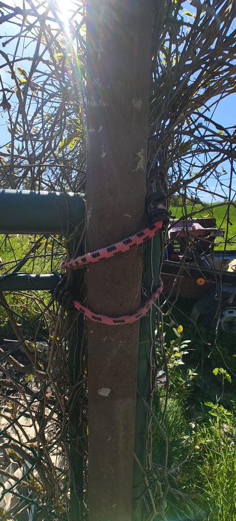
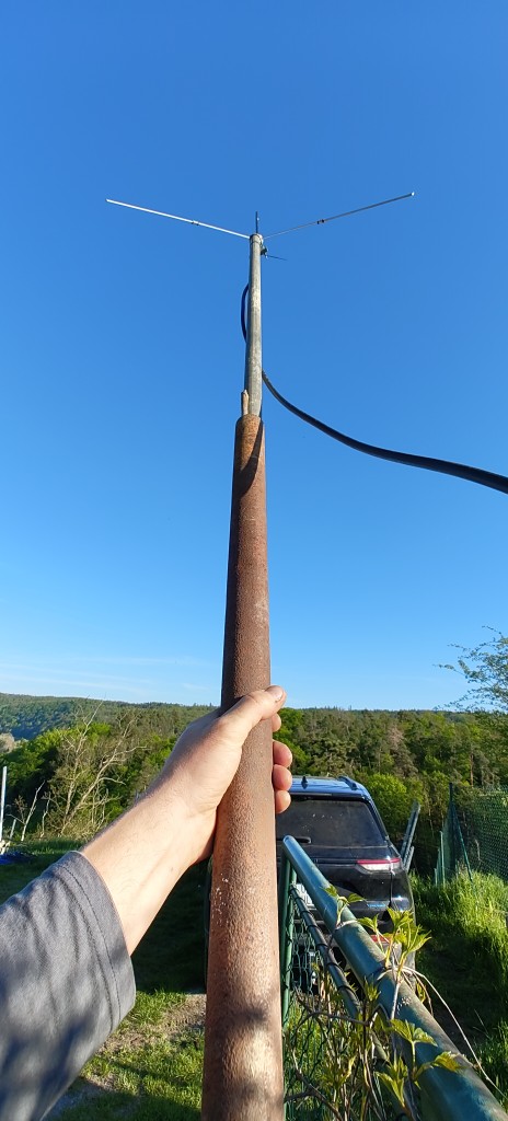
Antenna service area example
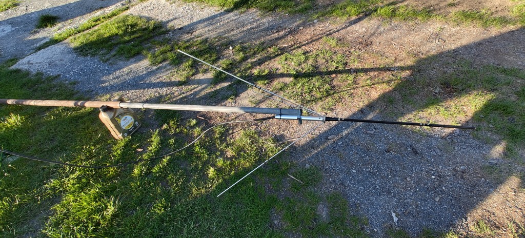
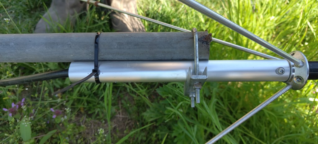
Antenna to the pol detail, use binding tape or wire for more secure connection
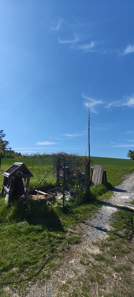
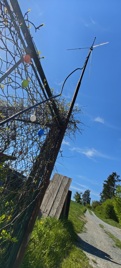
Antenna place with safe and easy hold-on and hold-off
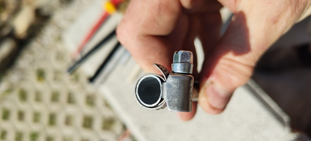
Mounting base example
Easy mounting detail
Measuring place in a shade of the car
¶ Tunning procedures
Although the most of the procedure is more or less the same in all cases, the results may vary in dependency of tunned frequency so i decided to split them.
¶ Tunning to the center frequencies - around 100MHz
This is usually the easiest proceedure, as the antenna is the best tunnable in the center frequency of it's functionality. If you are lucky, there will be no need to make any changes in antenna tip length and it is possible to use pre-tuned tips as the SWR "dip" is relatively wide. Also, radiators can be left at the original lengths or small change in length can be made just using original nuts. Shorter lenghts for higher frequencies, longeer for lower frequencies.
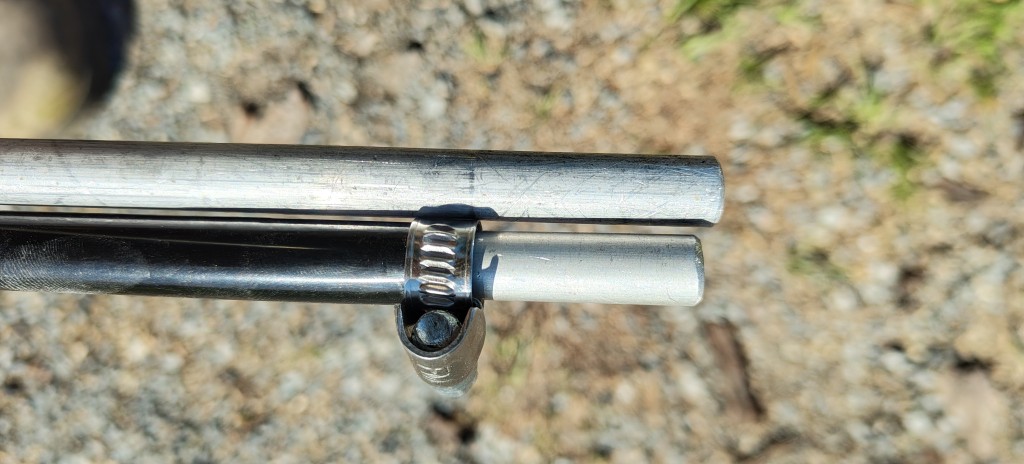
Remove antenna tip cover and insert metallic binding
Insert adjustable rod into the tip and fasten it enough to hold on place but still easy to move
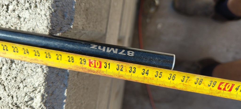
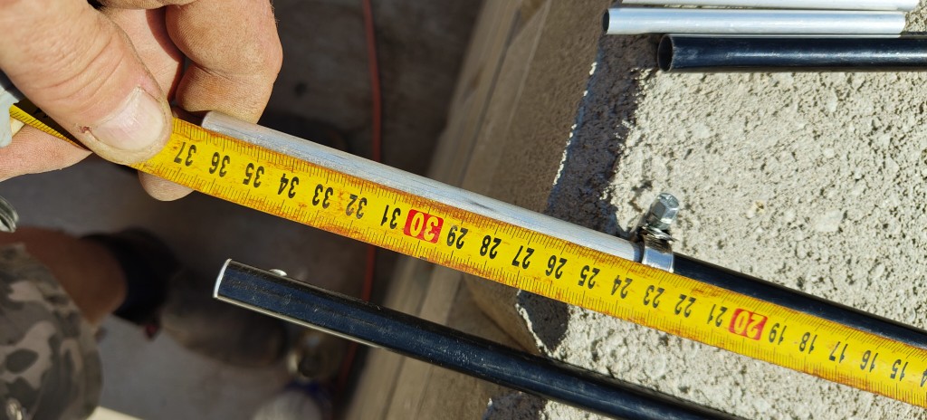
Estimate the length of the tip. Each 1MHz equals cca 4mm of length
Put antenna into a servicing position and instal tip of calculated length (100MHz in this case)
Shorten radiator lenth to minimal for this frequency
Rise antenna safelly and use bindigns to keep it fastened
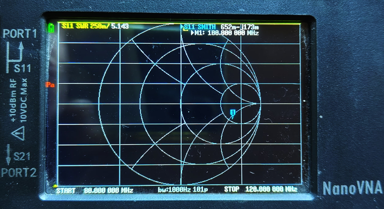
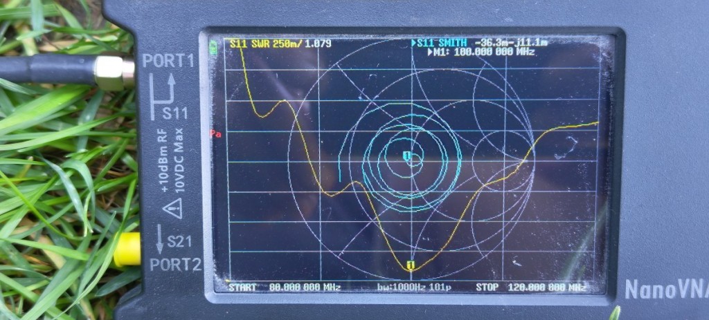
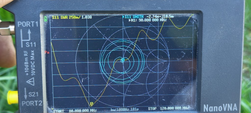
Connect VNA with first preset (80-120MHz) and check SWR
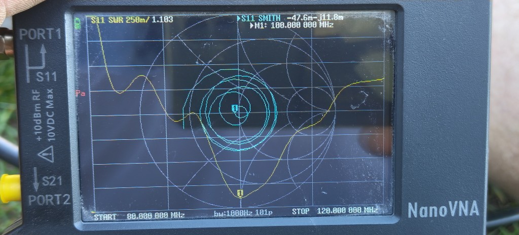
As you can see, we were lucky at the first measurement. Also, dip is relativelly wide so it should work good even with some ambient changes
Tip length adust for -3mm
Adjusted measurement
As you can see, thereare no major changes on this frequency as it's the best tunnable area. We see a bit improving on a higher frequencies. So let's try move this improving to lower frequencies
Enlarged radiators
Adjusted measurement
And voila! We got even better readings @100MHz
You may repeat those tunning a few times to get best results. The desired frequency suppose to be at the dip center. Tunning SWR < 1.1 is not necessary and might became tricky. Note that tip and radiator length must be in a coincidence even that length of the tip is major for frequency and radiator length is major for SWR. The length changes affects both parametters and you must be carefull with that and do small changes and observe how it reacts. If dip splits to a two dips, that means that there is too much difference in both lengths and you must correct them to be more close. Or, if the SWR is okay, you may use this behaving as more wide band transmitt antenne. But be carefull with that as antenna is a resonant component and two dips can easilly sweeps somewhere else with ambient enviromet changes as the resonance of two poles is not that stable.
What happens if I shorten pol for cca 1m?
Pol height changes influence
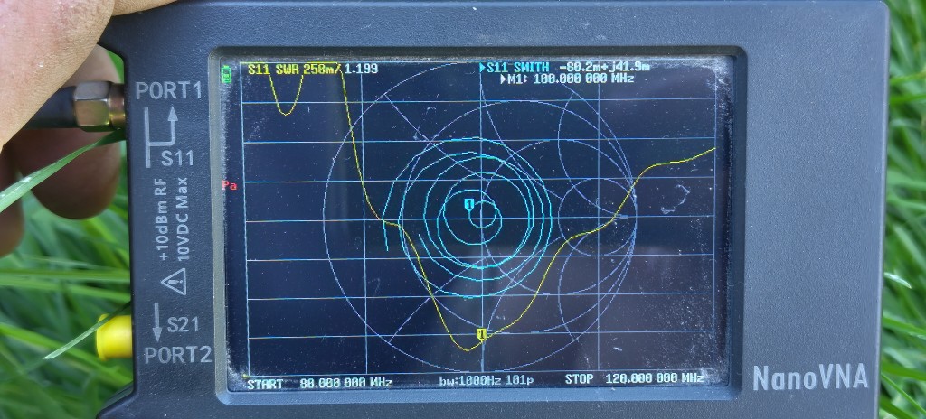
That's weird isn't it? That's the physic. Closer antenna position to the ground causes capacity increasing that results in lower resonant frequency. That's the reason to use as much similliary pol for reference measurement. Note that this tunning is also usefull as it's bellow SWR 1.2 Also, if you take a look at resonancy graph (cyan) you see that we are on a stable position so tunning suppose to be stable.
¶ Tuning the low frequencies - close to 87,5MHz
Tuning to low frequencies is a more complicated procedure, as the antena is off it's best tunable area. Also, radiator length must be enlarged / extended by 2 to 4cm more than original lenght to get SWR < 1,2.
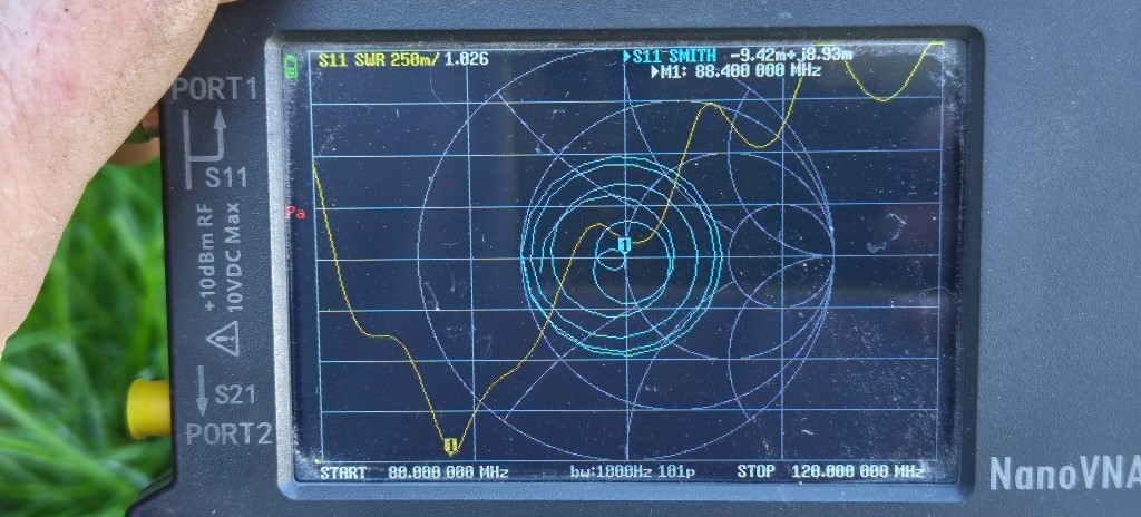
We are about to tune the same antenna to 88MHz. So recalculate tip length first
Tip enlarge /extend to the recalculated length
Calculated length measurement
We see that we are 2MHz higher than we needed. So let's try to adjust more. As we are at very low frequency, i would expect that radiator should be enlarged also.
Note: not described here, but if you would continue to enlarge tip, you would get two resonant dips
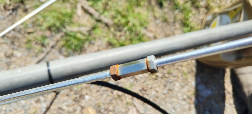
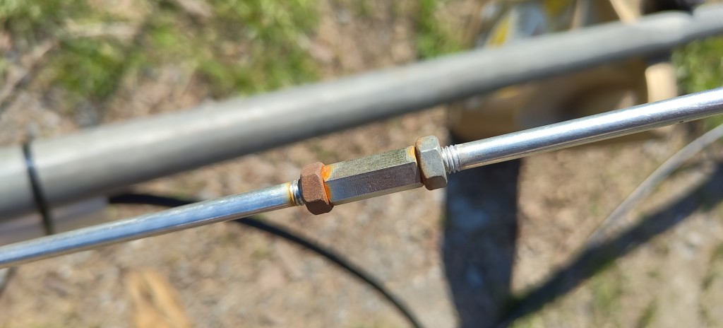
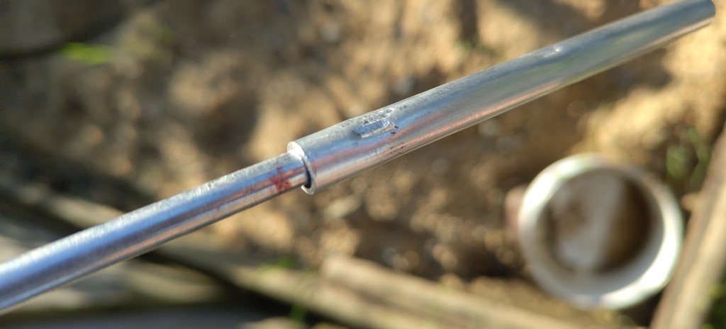
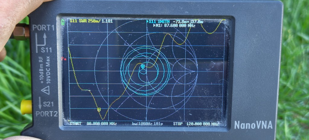
Radiator enlarging for 20mm
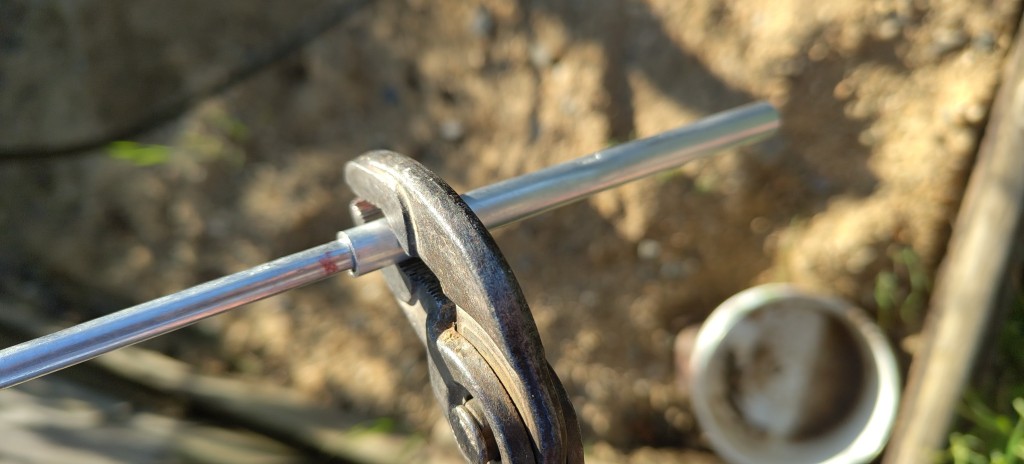
Use pliers or crimping tools to squeeze aluminium tube to hold firmly on a radiators. Use this for all three radiators! You may use sticky tape to hold tubes on a position, but for final installation the mechanically firming is best. You may use tape also, but every time use firm mechanical contact. Squeeze tube on more places in angle of 180deg, it helps. Use colored pen to make a marks of zero and next centimeters to remember the position.
Enlarged radiator
Enlarged measurement
That seems very nice. But keep in mind, that the dip is very thin and have step edges so environment can cause detunning of this ideal place. This is because antenna is in good resonancy, but on the edge of its working area.
This is situation on 87,5MHz
Radiators enlarged/extended from +20mm to +40mm
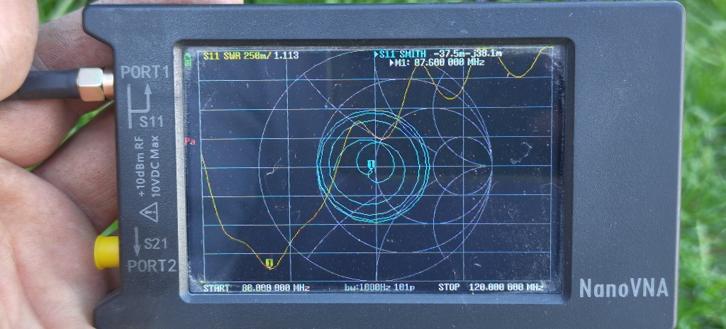
We put both resonances a bit off themselves. That means, we have a bit poorer SWR at the dip, but it improved at 87,5MHz . What is also important, dip is more wide and not that steep. This tunning can be used for even lower frequencies. You may play with that more, but i would recommend more tunning in field, that means with real conditions.
¶ Tunning to the high frequencies - close to 108MHz
Tuning to high frequencies is also a more complicated procedure, as the antenna is off it's best tunable range. Radiators in this case suppose to be in shortest length, you can also remove small bolts and use just the largest one to get more mm's to be shorten. I'm not recommending to cut radiators as their enlarging/lenghtening is problematic. In all my tests I got SWR around 1.1 on frequencies up to 106MHz with original radiator sizes.
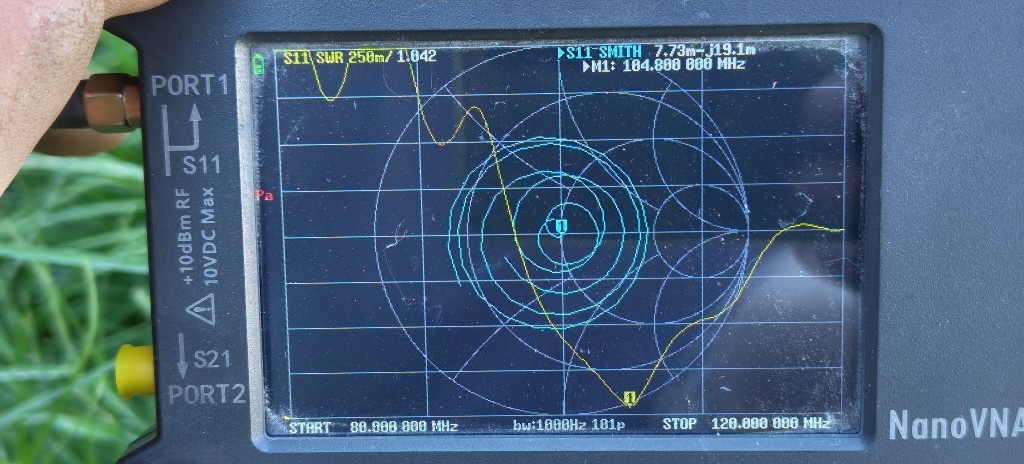
High frequency tip

Original tip used measuring

As you can see, we got something like 104MHz with 107MHz calibrated tip.
So we cut off 10mm off the tip that suppose give us 2-3MHz in advance
And got these results
As we see it's not that much, we got something like 105MHz. Also, the dip is nice and strong that means we have both resonaces on the same frequency. To go higher, cutting off the tip for another 10mm is necessary as well as radiators shorten for a few milimetters.
¶ Don't forget
- ensure that antenna is mechanically fitted strong to the pole.
- ensure that all mechanical antenna parts are screwed in tightly
- use UV resistant tape to fix radiator tubes before mechanical fitting by crimping. You may also use glue to fix them on radiator
- use more bindigs than original one
- use plastic bidings for a cable to the pole
- always use NANO-VNA to check antenna after installation
- document the installation: take photos of antenna, NANO-VNA screen photos etc.
- perform transmission test, take a photo of a service screen showing power values. Check if values are okay. If not sure, contact technical group
- lastly, put back plastic tip cover to protect tube from rain watter

![]() Important note: it's not recommended to use tips with testing rods for long time. It is always recommended to use tips cut to the desired length for long term use. Always cut the tip a few milimeters at a time so as not to exceeded the desired frequency. Only cut the antenna tip IN THE FIELD, at the installation location to avoid making mistake in final frequency tuning. Note that successfully tunning with VNA does not mean that it's going to be exactly tunned with BB3. The reason is, that VNA is calibrated to 50Ohms exactly for full band, but BB3 transmitter is NOT linear and it's impedance changes a bit over the band. That means, that some small changes in tunning can be expected when antenna connected to the BB3.
Important note: it's not recommended to use tips with testing rods for long time. It is always recommended to use tips cut to the desired length for long term use. Always cut the tip a few milimeters at a time so as not to exceeded the desired frequency. Only cut the antenna tip IN THE FIELD, at the installation location to avoid making mistake in final frequency tuning. Note that successfully tunning with VNA does not mean that it's going to be exactly tunned with BB3. The reason is, that VNA is calibrated to 50Ohms exactly for full band, but BB3 transmitter is NOT linear and it's impedance changes a bit over the band. That means, that some small changes in tunning can be expected when antenna connected to the BB3.