¶ Service menu 0
Default menu - system overview
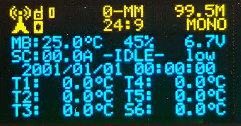
- Line 1: mainboard temperature; mainboard humidity; mainboard supply voltage
- Line 2: System current(N/A); MP3 status; System voltage
- Line 3: System date and time
- Line 4 - 6: 1-Wire sensors temperatures
Button activity: manual trigger
¶ Service menu 1
FM receiver info
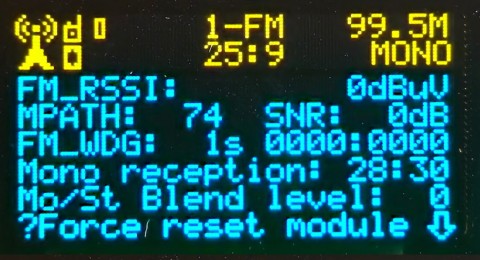
- Line 1: FM radio signal strength
- Line 2: multipath value; signal to noise ratio
- Line 3: fm watchdog, resets automatically. If reaches preset value [sec] force module reboot
- Line 4: mono receprtion time synce last reporting/trigger
- Line 5: stereo indicator
Button activity: force Fm receiver module reset
Note: ![]() if no valid FM carrier, quiet or noise detected, module reset is forced automatically
if no valid FM carrier, quiet or noise detected, module reset is forced automatically
¶ Service menu 2
System time overview
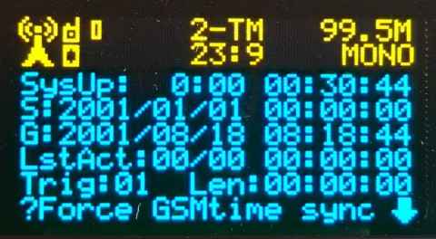
- Line 1: system uptime since last reboot
- Line 2: system time
- Line 3: GSM network time (used for synchrnization)
- Line 4: last date/time of active trigger
- Line 5: type of trigger and play length
Button activity: force manual time synchronization
Note: automated synchronization can be set on main display menu. Set to 00:00:01 time by default
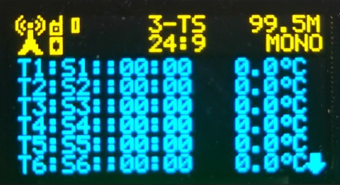
¶ Service menu 3
Temperature sensors assigning to positions; actual temperatures. last two bytes of sensor ID displayed behind assigning
¶ Service menu 4
GSM module report
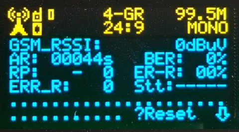
- Line 1: GSM radio signal strength
- Line 2: automatic reboot counter; force resets if GSM module does not answer; bit error rate in GPRS data connection
- Line 3: reporting pointer value
- Line 4: error rate based on retransmits
- Line 5: error repeats; number of retransmissions if data connection is poor; GSM status when reports
Button activity: force GSM module reboot
¶ Service menu 5
Temperature sensors list - 1-Wire addressing

Button activity: force 1-Wire sensors acquire and save
![]() Note: use this only when you know what you are doing. This setting automatically rewrite previous records and if some of sensor(s) is removed,not working or exchanged, it may change sensors position and new sensor assigning is necessary
Note: use this only when you know what you are doing. This setting automatically rewrite previous records and if some of sensor(s) is removed,not working or exchanged, it may change sensors position and new sensor assigning is necessary
¶ Service menu 6
Fans and sensors location in the BB3
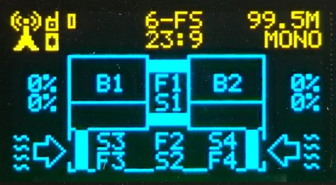
Fan speeds in [%]:
- left top FAN1
- left down FAN2
- right top FAN3
- right down FAN4
Button activity: force ventilator test
¶ Service menu 7
Logger memory status

- Line 1: address value of last writted report address
- Line 2: address value of last reported record
- Line 3: number of records to be reported (0 - all reported)
- Line 4: last report time
- Line 5: maximum number of records is 255. If exceeded, oldest reports start to be rewritten. This number identify amount of memory rollovers if they occurs
Button activity: force immediatelly reporting all remaining records
¶ Service menu 8
Active trigger - menu displays only when trigger is active
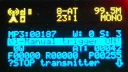
- Line 2: MP3 player/transmitter active time [=/10 in sec]; watchdog value
- Line 3: status line
- Line 4: curent transmitt power (not the preset one)
- Line 5: forward power (not in watts!!); return power (not in watts!); current power (not in watts!)
Button activity: stops transmitting