Monitoring device (MD) for FM signal quality monitoring
Radio Monitoring (RMS) for FM signal quality monitoring
Specially issued for FEM Nigeria
SW version: 1.06
HW version 2.1
Signal measurement:
- FM RSSI
- FM SNR
- FM multipath
- FM carrier
- GSM RSSI
- L, R, L+R, L-R audio level
Analyses:
- remote MONO
- remote noise
- audio mute
- modulation depth
- local MONO time
- remote MONO time
Advanced:
- Stereo DTMF decoding
- Audio recording
- GSM direct audio monitoring
Annotation:
- HW description
- Wirring diagram
- Specifications
- Top zone display descriptions
- Bottom zone display description
- Remote GSM configuration
- GSM commands table
- SW upgrade
- BBserver connection and data structure
¶ quickstart
No settings need to be configured. All settings for FEM Nigeria are pre-configured. So plugging-in any MICRO USB plug(s) to USB port should be enough to work normally if power consideration are passed [3]. Also attaching FM and GSM antenna is necessary to get proper signal and inserting SIM card with a GPRS data tarif is needed.
Working conditions:
To find the best working position, there are four LED's from which the two LEDs in the bottom left of the MD are used to determine overall FM and GSM signal quality. So even non-experienced users can determine best antenna positioning for either the FM or GSM antenna.
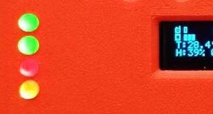 Power supply state (must always be green) -->
DTMF/BT power state (green if enabled) ------>
FM receiver signal quality indicator --------------->
GSM module signal quality indicator ------------->
Signal quality indicator:
Determines and displays signal quality according to more variables and conditions. To get ideal conditions, indicator must be Yelow/Green. If RED, signal quality is low and services are not working properly.
Setting-up propper conditions:
-Simply move FM or GSM antenna (according to proper signal indicator) to a diferrent location.
-Ensure antenna is properly installed on a flat metallic plate of size >20x20cm
-Use higher gain antenna or more quality antennas
If you are not succesful in getting a strong signal, BB installation is not recommended or special working conditions and accesories must be considerred
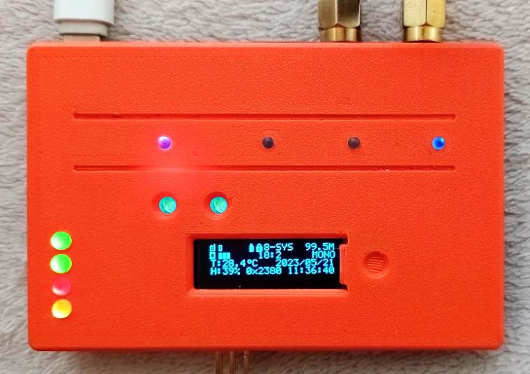
¶ 1. HW descriptions
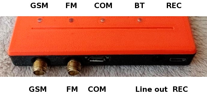
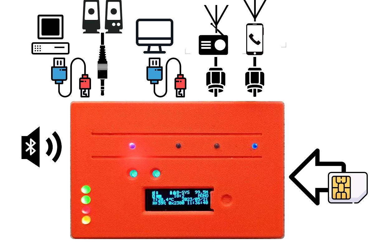
Monitoring device (MD) has following interfaces:
- USB micro plug for digital audio recorder
- USB micro plug for serial monitoring console
- STEREO audio jack 3,5mm for audio Line-out
- SMA plug for FM receiving antenna
- SMA plug for GSM antenna
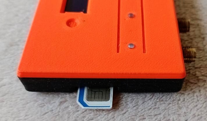
- SIM card slot
- programming plug
- menu navigating button
- reset button
- Bluetooth (BT) device select button
- OLED 128x32 display
- 8x LED indicators
Top indicators (left to right):
- BT pairing
- serial communication

- FM MONO/STEREO status
- GSM status
Left indicators (top to bottom):
- 5V supply voltage
- DTMF/BT on/off
- FM signal status
- GSM signal status
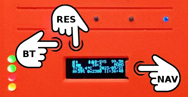
Buttons (left to right):
- BT pairing
- RESet button
- OLED menu NAVigation
¶ 2. wiring diagram
MD is designed to operate from a USB 5V/500mA source through one or both of the USB micro ports. Using both plugs in paralel is recommended to get lowest wire resistance. MD is tolerant up to 6 VDC, voltage below 4,7 VDC or voltage supplies with low current source ability can cause the GSM module to restart/not operate.
Audio output jack can feed any of Line-in inputs with input resistance >1 kOhm, 10 kOhm is optimal.
Use of any FM receiving 50 Ohm antenna supported, active antennas (with preamplifier) can also be used.
Any standard type of 800/1600MHz GSM antenna can be used. Use of small non-wired antennas is not recomended if GSM signal is weak beacause of low gain and also, high radiation power can cause MD to get stuck and the MD then needs to be restarted manually (this must be considered according to local conditions). Usage of 6-12 dB GSM antennas with pigtail is recommended to get the best GSM signal. Note, that most of the cables have significant attenuation for each meter of the cable, so no longer than 2 meters of the cable and no lower gain than 6 dB of gain for antenas is recommended.
Use a SIM card in 12mm of size - “Micro SIM” only.
¶ 3. Specifications
- Recommended supply voltage: 5,1 VDC; designed to operate from USB powerbank 5 000 mAh - 10 000 mAh
- Absolute maximum supply voltage range: 4,7 - 6,4 VDC
- Supply current: 30<40 mA (no DTMF, no digital audio recorder, no BT)
- Supply current: <50 mA (DTMF on, BT not connected )
- Supply current: <60 mA (DTMF on, BT connected )
- Supply current <100 mA if DTMF, BT and audio REC active
- Supply current >200 mA if GSM/GPRS is operating
- FM band: 87,5 - 108 MHz
- GSM band 800/1600; GPRS data connection
- Communication protocol: UDP
- Serial settings: 9600/8N1
- Line out: 1Vpp max, 10 kOhm
- programming slot: 6pin AVRdude/ATMEGA328
The monitoring device works as a pre-configured device which cannot be set-up locally. Implemented display shows main information and some configuration settings, but only a few of them can be set directly. To fully set-up the device, you must use SMS commands as described in[5]. All settings are valid when they are received and a confirmation status is reported back to the telephone number from which the command was sent. Those settings are valid until the device is rebooted. After reboot, values stored in internal flash memory are loaded back to the MD and all unsaved changes are lost. To save changes, a special command to save current values must be applied. Previous settings are lost and replaced by current ones.
The OLED display has two zones, top and bottom. Top zone has two lines displaying the same content in all user menus. Bottom zone has four lines and content is changed by browsing the menus.
The menu navigation button has two diferrent lengths of press. Short press for menu navigation when the screen is locked and changing values/activating when screen is unlocked. Long press lock/unlock the screen.
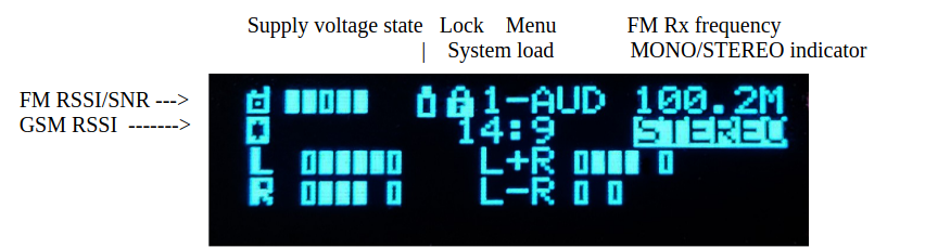
¶ 4. Top zone display description
The top zone of the display area displays the same values through the whole menu structure. It consists of two lines divided into three areas: left, middle, right. The left area contains signal info, middle area system information and right belongs to FM receiver.
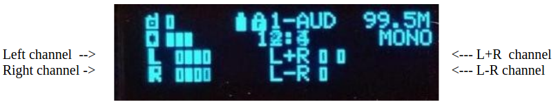
¶ 5. Bottom zone display description
Menu 1 – Audio levels (default menu)
Audio levels are represented by bars. Filled bars represent current values, empty bars represent zero and maximum values. All audio levels are maximum values of audio channels averaged throughout 100ms. Added channel L+R is a source of MONO signal, subtracted channel L-R is source of phase shifted channel used for DTMF STEREO decoding and as a source for remote MONO analysis.
Button activity: NONE
Menu 2 – Averaged values for analytic purposes
These signals are long time averages of maximum values to remove the influence of random noise on the signal. DS equals maximum dynamic span counted from L+R signal and used to analyse dynamic envelope for noise detection. MS is the maximum value for observing period. Averaging time can be optionally set by an SMS command. Observing period is the same as reporting period and can also be changed by an SMS command. A, B, A_B and A-B values repesents L and R averaged levels for averaging time and they are used to analyse modulation level and STEREO disbalance
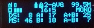
Button activity: NONE
Menu 3 – A/D converter
These values represent instant values of A/D converters. 1=Left channel; 2=Right channel; 3=L+R; 4=L-R; 5=supply voltage; 6=number of low_voltage events since last power-on or reset
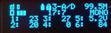
Button activity: RESET to factory settings
Menu 4 – FM receiver
This menu displays basic FM receiver settings.
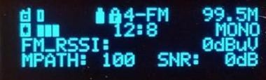
Button activity: Restart FM module
Menu 5 – DTMF decoder
DTMF min are minimum characters in required to activate the trigger. Max is maximum value of DTMF characters to activate the trigger. Rx code displays received code. There are no blacklists or preset codes, so any received code within the character range activates the trigger if DTMF decoder is ON. Maximum time for characters bunch is preset to 4s.
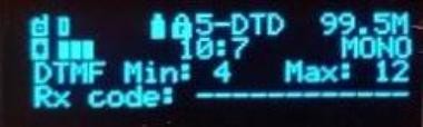
Button activity: Toggle ON/OFF DTMF/BT modules
Menu 6 – GSM settings
Rt is time in seconds for periodic frame 0x80 trasmission. Wd is GSM watchdog, represented in seconds x10. Scrolling values on the bottom line show all settings needed for data connection: Bottom right value shows current PIN to use remote SMS commands. If the value blinks, there were changes via SMS applied and not saved.
APN – internet provider APN name 
USR – username (if applied)
PAS – password (if applied)
SIP – BBserver IP address
CON – connection protocol and port
Button activity: if unlocked, bottom line displays GSM communication log. Pressing button when unlocked toggles the GSM module ON/OFF.
Note: it takes up to 30s to shutdown/enable the GSM module. Also, enabling and disabling module is NOT saved, its just for debugging and GSM reset purposes.
Menu 7 – Audio multiplexer
Displays, enables and changes audio routing in the MD. There are two main audio routes. One to the GSM module for MD audio monitoring and second for the DTMF decoder. The DTMF decoder can be fed by L+R or L-R signal, GSM can be switched between DTMF route and audio L/R route.
DTMF – source for DTMF decoder 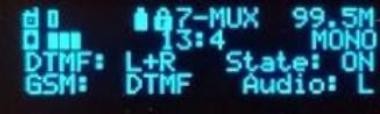
GSM – select source for audio input
State – DTMF decoder status
Audio – source for GSM mux
Button activity: toggle all multiplexer settings (8 states)
Menu 8 – System menu
Displays general information such as system temperature, humidity, date/time and MD_ID
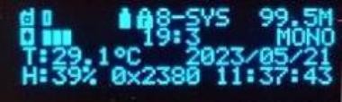
Button activity: if MD_ID blinks, it means some settings are not saved, when pressing the button, current values are saved to FLASH when unlocked
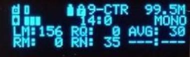
Menu 9 – Counters
Display main internal and statistic counter's state.
LM – local MONO time [s]; increments when no STEREO carrier detected. Resets every Tx period
RM – remote MONO time [s]; increments when remote MONO signal over STEREO carrier detected
RQ – remote QUIET detected, increments when quiet over MO/ST carrier detected
RN – remote noise detected; increments when dynamic treshold reached (testing version)
AVG – averaging counter state
Menu 0 – Screensaver
Screensaver is activated avery screensaver delay when no button pressed. Cannot be disabled because of power saving procedure. Delay can be set through an SMS command.
¶ 6. Remote GSM configurations
MD can be configured and also monitored by remote SMS commands. If these commands are succesfully decoded by the MD, it replies with local time reception and command number. All settings made by remote SMS config are immediatelly activated. Changes to be stored, must be saved using local or remote save command, otherwise they are lost when rebooting. Delivering SMS can take a while, especially when GSM signal is low. Also, some commands can be missed if MD is busy at the time of reception. If you don't receive an SMS confirmation within reasonable time, try resending the command. Note: every command is stored into a GSM module. If a new command is resent after there is no confirmation received and previous command is still waiting to be executed, the first waiting command will be executed as soon as any new command(s) are received and all other commands received and pending are ignored and erased.