- remove battery cover frst to allow access to the shaft from top side.
- disconnect speaker plugs
- remove mainboard, GSM cable can stay connected (no lid removing needed), just flip mainboard righ side over transmit module
- remove power supply shielding, the best is to start front side and pull it of he magnets to cca 30degrees
- note or photo LED contacts position on a protection switches, they secured mechanically just by shield pressure
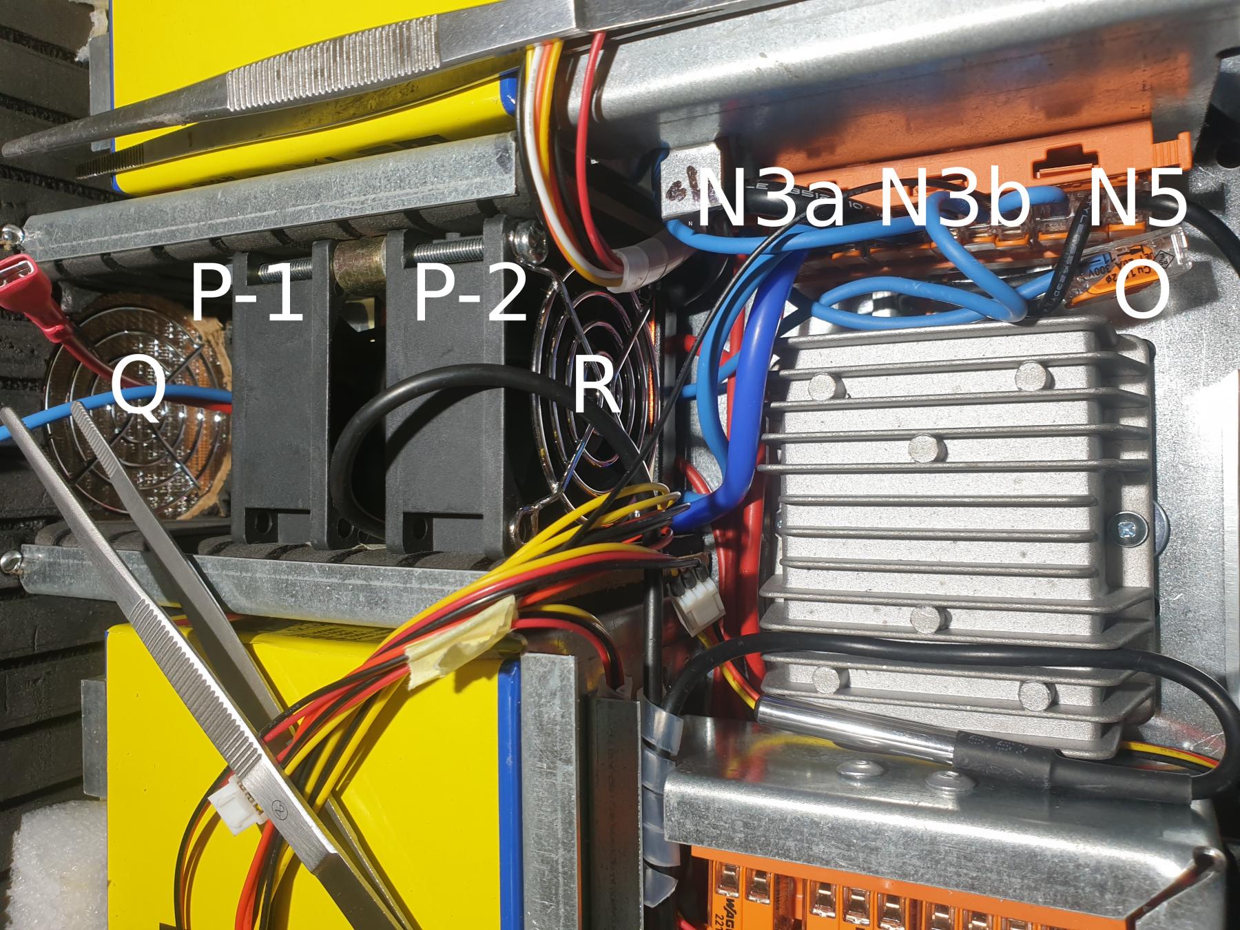
- observe and note how wires are lead around the fan bunch. Also, note that temperature sensor cable has its position in FAN separator. Make a photo(s) for yourselves to remember a position
- pull central FANs (P1 and P2) up and towards the center in a slope. There is no any mechanical secure, simply use force and mind all cables around as the metal frame edges are very sharp
- as you exchange FAN(s) from a pair, prepare cable bundle in proper order as it was before. It's recommended to place dot markings on a FAN wire plugs to keep proper sequence
- note that there is a dip for temperature sensor in FAN separator which must be on left side down and proper orientation
- put FAN wires on their position in fan dips, you may secure them by sticky tape.
- push temperature sensor into FAN separator hole and bend cable into separator position
- push FANs into their position between foam walls, hold temperature sensor cable on its position until is secured by foam pressure
- watch all wires to keep them off the sharp edges
- ensure that FANs sits properly at their position and there are no squeezed wires bellow FANs
- adjust cable bunch position and shape
- insert power shielding back. The best it to insert back of the shield first, then plug LED contacts into their position on a switches and pull it down. Take care of wires again, especially LED wires can be easilly cutted in between shield and switches